


Brain-Computer-Interface controlled robot via RaspberryPi and PiEEG | Summary
04 Feb 2022 | Paper Review Brain-Computer Interfaces Signal Processing Robotic ControlContents
This article explains the key points of Brain-Computer-Interface controlled robot via RaspberryPi and PiEEG.
- 2022-02-04 (arXiv)
- Rakhmatulin, Ildar, Volkl, Sebastian.
- Paper
Summary
- The paper investigates how to control external objects using inexpensive electroencephalogram (EEG) equipment, which measures electrical signals at the scalp. In a blink-controlled demonstration, the device worked correctly in 8 out of 10 cases in each of two frequency ranges; no competing system was evaluated.
- PiEEG combines a Raspberry Pi shield with open-source software that filters the signal and uses a Fast Fourier Transform, a method for decomposing a signal into frequency components. The authors used the resulting signals to control light-emitting diodes (LEDs) and a radio-controlled toy, reporting a 1-second software delay.
- The demonstration relies on blink artifacts, signal distortions caused by blinking, and requires user-specific frequency and amplitude settings. The paper does not report participant counts or a detailed trial protocol, limiting interpretation of the reported success rate.
Introduction
The authors aim to lower the technical and cost barriers to experimenting with a brain-computer interface (BCI), a system that uses measured signals to control external devices. They treat blinks, normally unwanted EEG artifacts, as intentional control signals and acknowledge limitations including low efficiency and restricted freedom of action.
1. Technical details
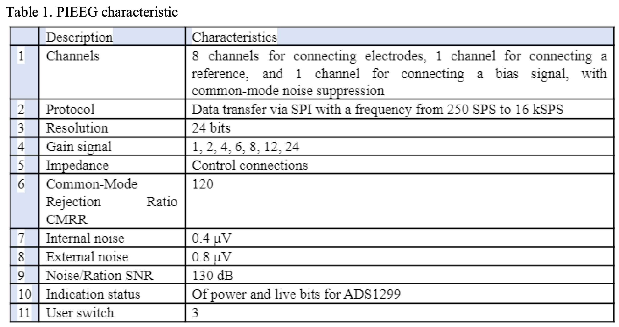
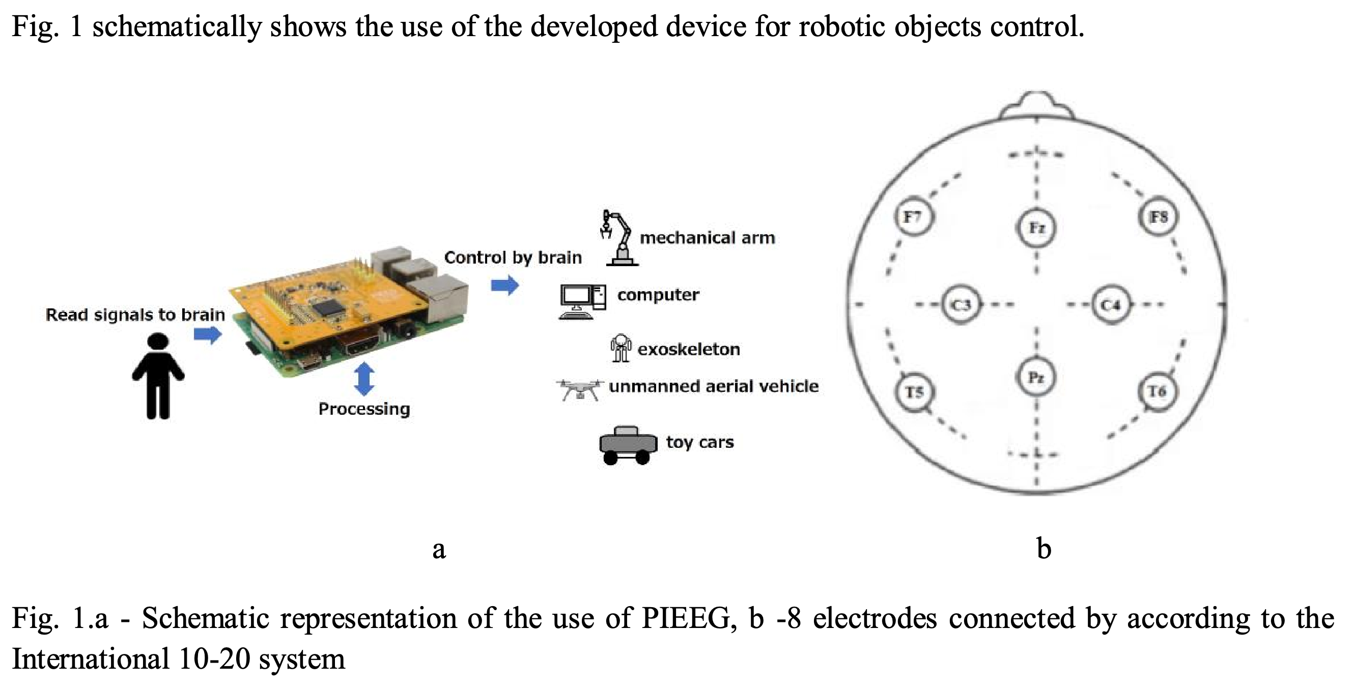
The PiEEG shield provides eight electrode channels plus reference and bias connections, 24-bit resolution, and Serial Peripheral Interface (SPI) data transfer at 250 samples per second (SPS) to 16 kSPS. The authors use dry electrodes and illustrate placement according to the International 10-20 system, a scalp electrode placement scheme.
The specifications identify the acquisition hardware behind the demonstration, including eight electrode channels, 24-bit resolution, and the stated 250 SPS to 16 kSPS transfer range.
The left panel sketches signal acquisition and possible controlled devices; the right panel shows eight scalp positions in the International 10-20 system.
2. Software
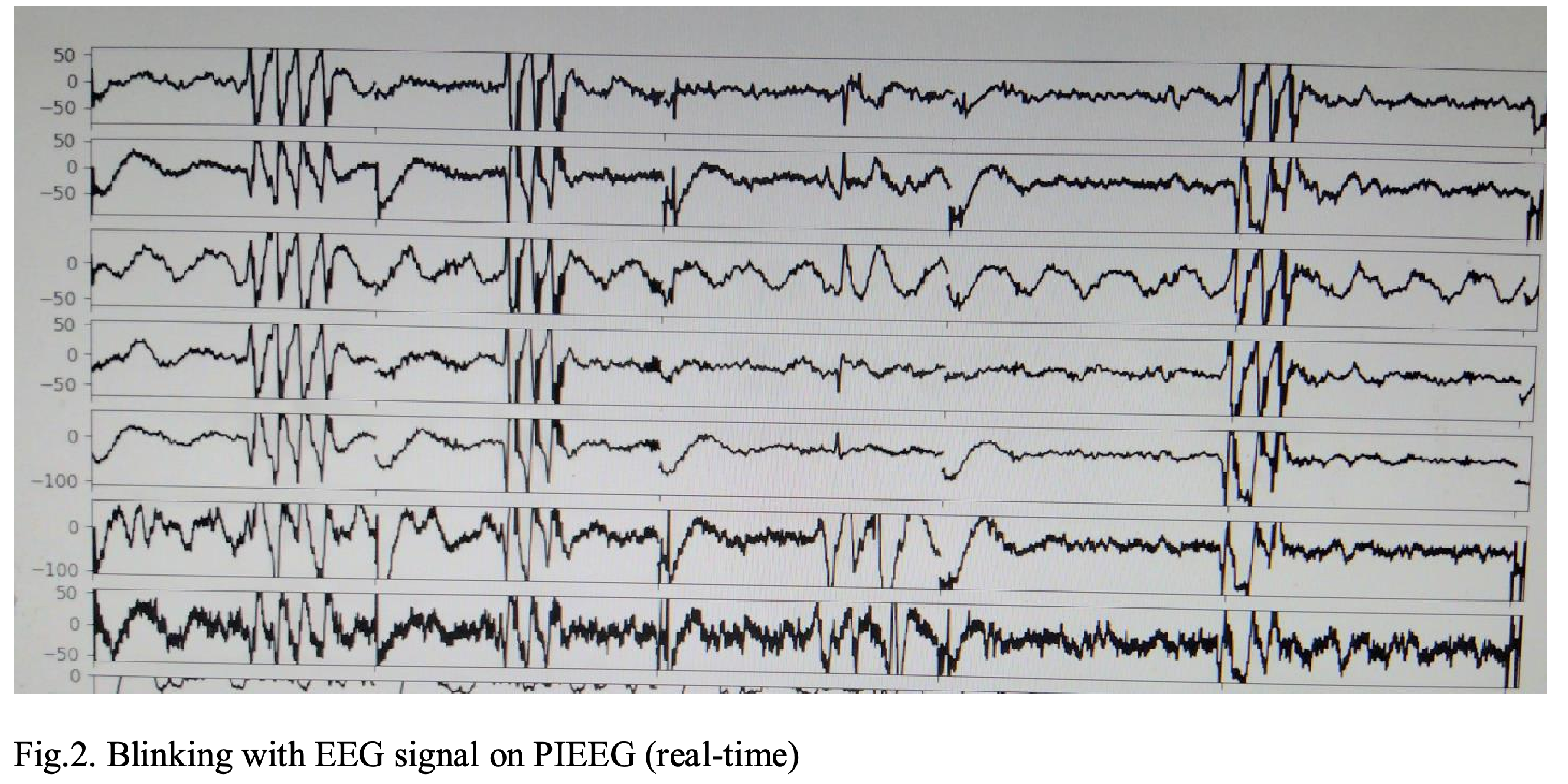
A C static library connects the Raspberry Pi to the analog-digital converter (ADC), which digitizes the electrode signals, and configures its sampling rate and registers; Python handles subsequent signal processing. The authors report that blink responses appeared on all channels and selected a single electrode at Fz, a scalp position in the 10-20 system, for the demonstration.
The simultaneous deflections across the displayed channels support the authors' choice to use one Fz electrode for detecting blinks.
3.1 Device setup
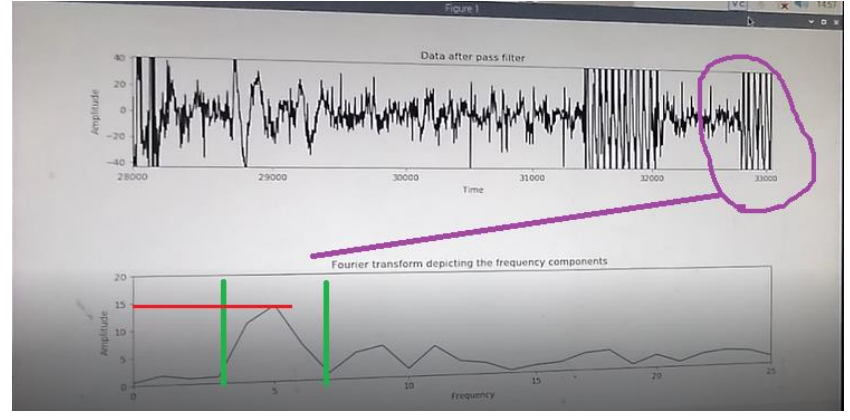
The setup connects PiEEG to a Raspberry Pi 3 or 4 powered by a 5 V battery; the paper explicitly instructs readers not to use the power network. A 1–30 Hz bandpass filter retains the selected signal frequencies, and the Fast Fourier Transform provides frequency components for threshold-based detection.
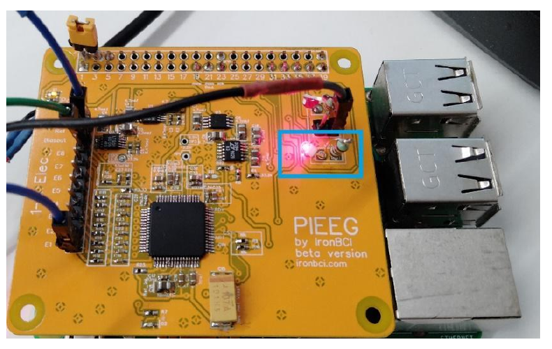
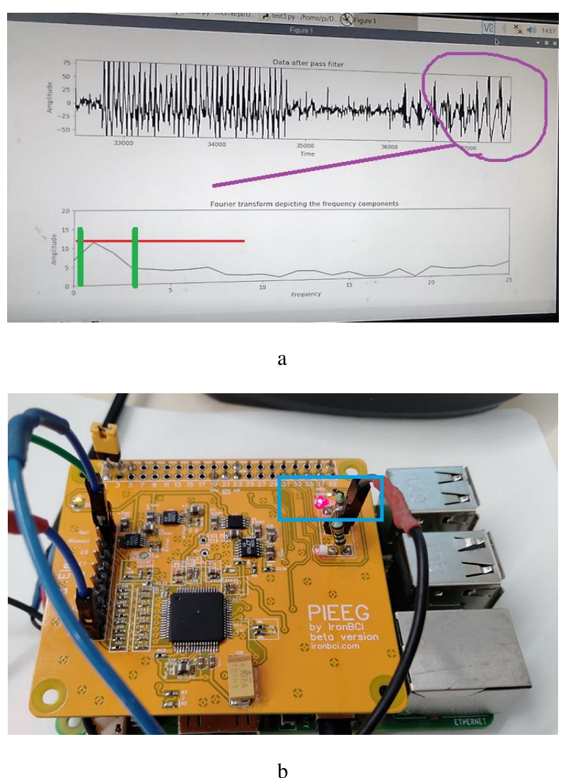
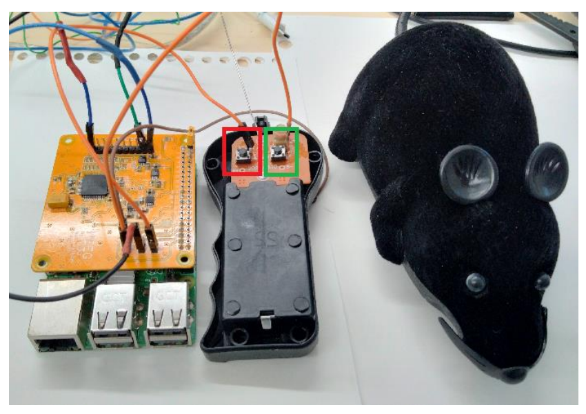
The two LED demonstrations monitor 3–7 Hz and 1–3 Hz, with general-purpose input/output (GPIO) pins 31 and 35 respectively in GPIO.BOARD mode. The authors report 8 correct cases out of 10 for both ranges and successful toy movement through connections to its radio remote-control buttons; they do not specify the number of participants or provide a separate quantified toy-control result.
The signal plot, frequency spectrum, threshold and illuminated board LED illustrate the 3–7 Hz control condition, using output 31.
A second spectrum and illuminated LED illustrate the 1–3 Hz condition, using output 35.
Wires connect the PiEEG setup to two marked buttons on a toy's radio remote, showing how detected signals were routed to an external controller.
Conclusion
The authors describe blink control as an accessible demonstration and do not claim it is the best method for robot control. They report a 1-second real-time delay and note that direct SPI transfer avoids separate wireless or serial transmitters; they also describe potential connections to OrangePi and BananaPi boards.
Appendix
- The source code is available at https://github.com/Ildaron/EEGwithRaspberryPI/tree/master/Robot_control. The paper lists the GNU General Public License v3.0.
Brief Thoughts
The hardware and signal-processing description makes the demonstration concrete, but the small reported trial count and missing participant and protocol details do not establish reliability across users. The need to tune frequency and amplitude for each person, along with the reported 1-second delay, matters for practical use.